Products & Services
Brochure
Let’s Start Work
Together
Please feel free to contact us. We will get back to you with 1-2 business days. Or just call us now.
CONTACT US NOW
Please feel free to contact us. We will get back to you with 1-2 business days. Or just call us now.
As a company committed to energy efficiency and environmental sustainability, our goal is to provide products and services that address the needs of today’s world. As the threat of global warming continues to grow, we understand the importance of solutions that not only improve the environment, but also reduce operating costs for our clients.
Our experienced team of turbomachinery experts and culture of persistent innovation enabled us develop an extensive range of vapour fans & compressors for vapour compression, that provide adequate solutions for a variety of industry segments & applications. These vapour fans & compressors are designed with advanced technology and high-quality materials to ensure optimal performance, efficiency & reliability.
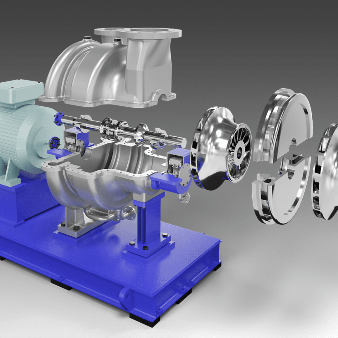
- Centrifugal Fans
- Centrifugal Compressors
- Axial Compressors
- Centrifugal Fans
- Centrifugal Compressors
- Axial Compressors
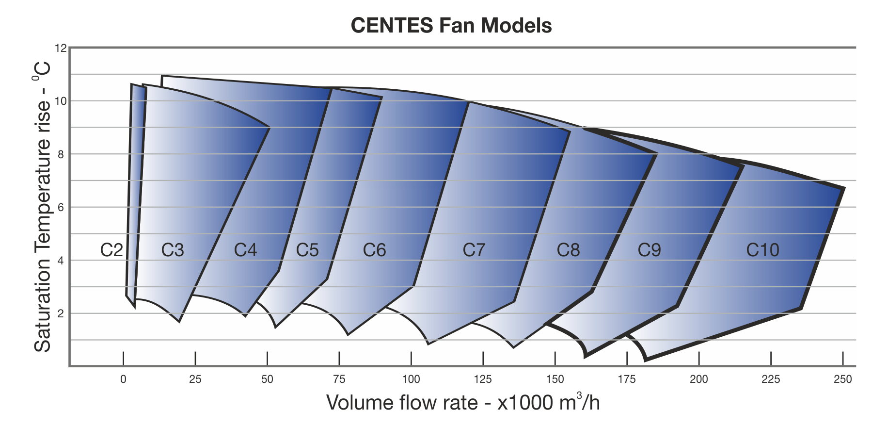
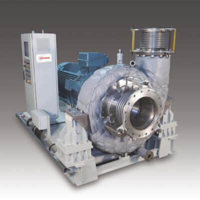
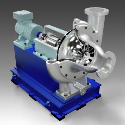
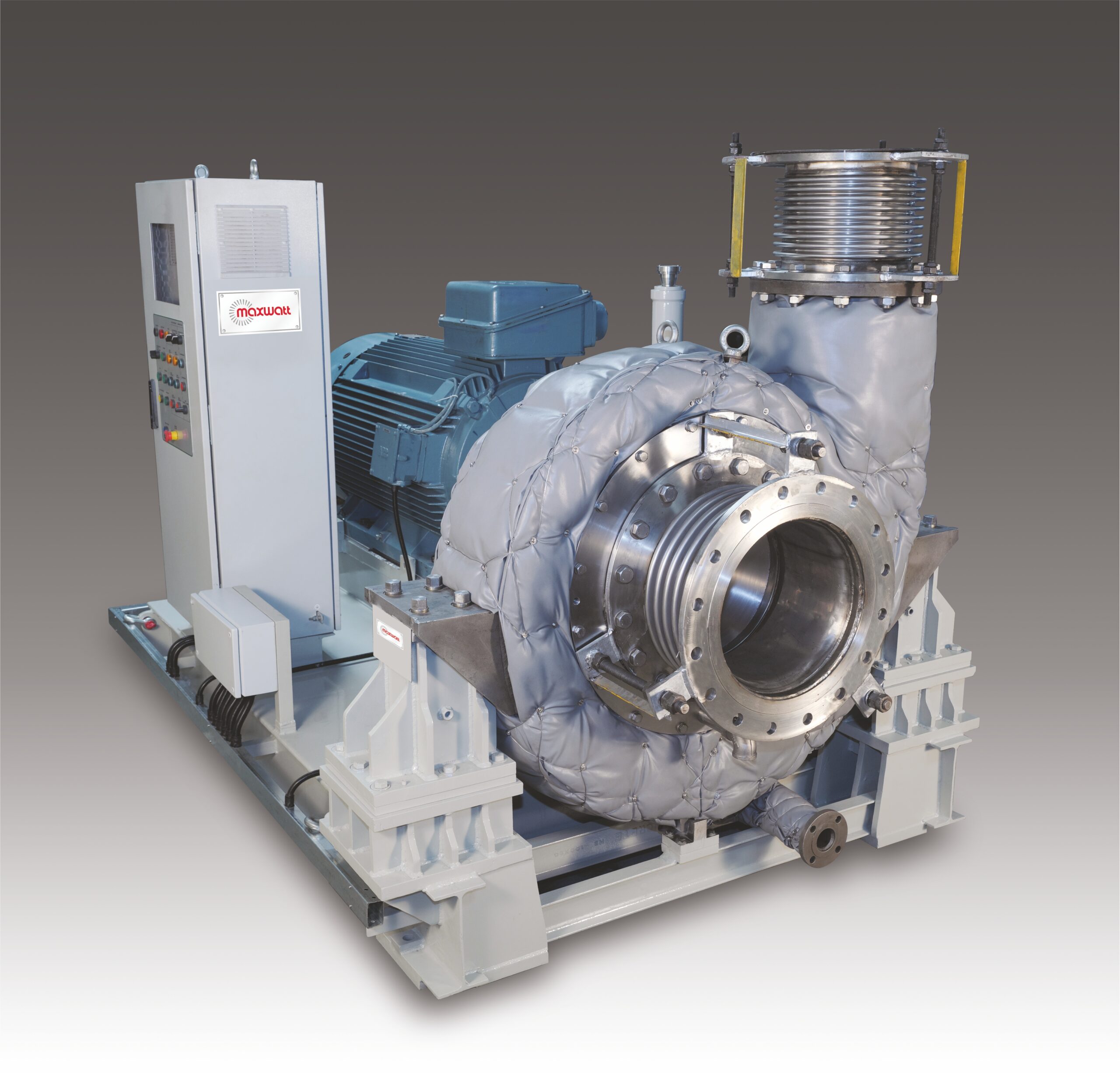
Maxwatt proudly presents Centrifugal Fans tailored for MVR applications, catering to vapor flows of up to 250,000 cubic meters per hour.
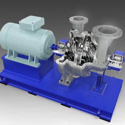
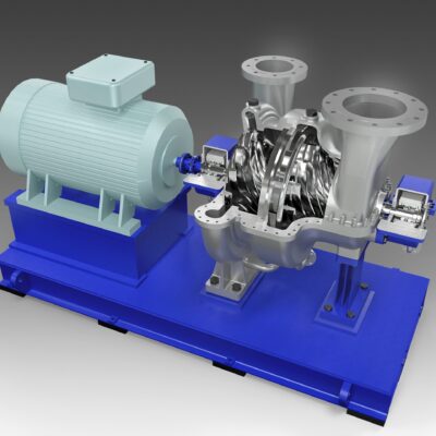
These robust centrifugal fans serve as dependable workhorses, ideally suited for an extensive spectrum of MVR applications that demand low pressure ratios. This includes critical processes such as Zero Liquid Discharge (ZLD), liquid effluent treatment, and product concentration. Our design and construction adhere to established features and industry best practices, ensuring a dependable and highly efficient operation.
Model and Rating
- Maximum Volumetric Flow - 200,000 M³/Hr @ 1 Bar, 100°C
- Maximum Saturation Temperature Rise - 10°C
Major Components / Design & Construction Features
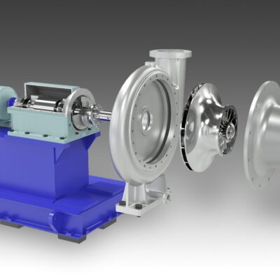
Volute Casing
Casing Construction
Casing Design Analysis


Material Selection
We carefully select the construction material based on your specific application requirements. Among the commonly used materials are Carbon Steel, SS 304, SS 316L, SS 316Ti, Duplex, and Super Duplex steel. Each material undergoes thorough laboratory testing to ensure that its chemical and physical properties align with the specified composition.
Fan Impeller
Impeller Construction
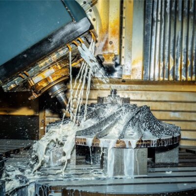
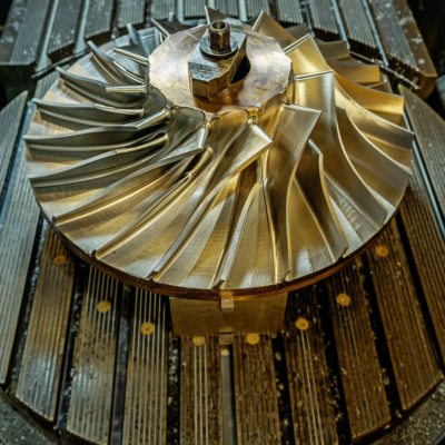
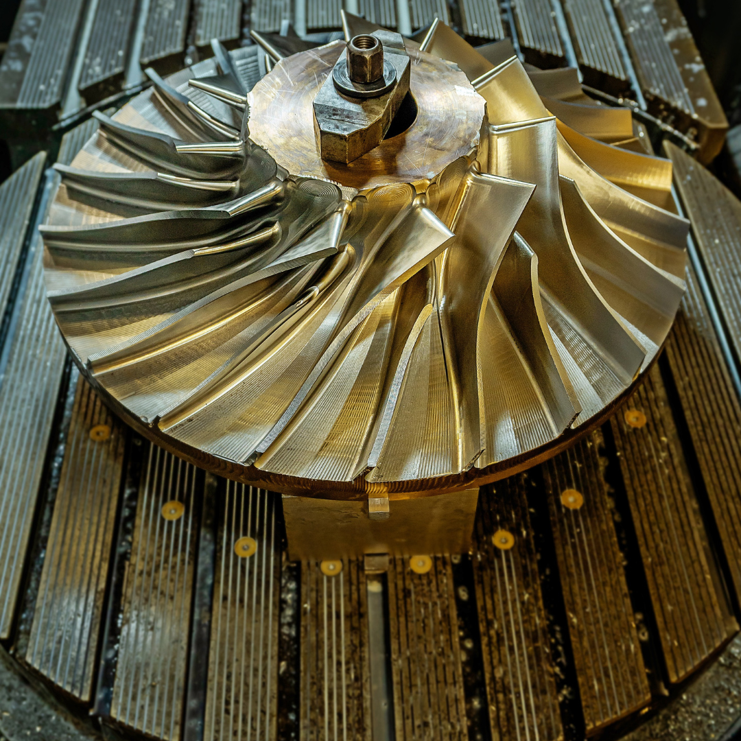
Impellers are manufactured using advanced techniques tailored to the flow rating. Smaller flow-rated impellers are typically 3D metal printed, while larger flow-rated ones are fabricated. The blade profiles also vary, with larger impellers featuring 2D profiles and smaller sizes employing 3D profiles. The design of the blades, including their shape, curvature, number, and angles, is meticulously chosen to optimize compression efficiency. Our focus on aerodynamic efficiency minimizes losses arising from turbulence and flow separation. Comprehensive Computational Fluid Dynamics (CFD) simulations are conducted to analyze flow patterns and fine-tune impeller designs, resulting in enhanced compressor performance and energy efficiency.


Material Selection
Material selection is driven by specific application requirements, with an emphasis on excellent mechanical properties. Commonly used materials include SS 304, SS 316L, SS 316Ti, 17-4 PH steel, Duplex, Super Duplex steel, and Titanium. Rigorous material inspections are conducted during manufacturing to ensure the absence of defects or flaws that might compromise the impeller’s integrity. Quality control measures, such as non-destructive testing (NDT) techniques like ultrasonic testing and dye penetrant inspection, are employed to verify the structural soundness of the impellers.
Stress Analysis
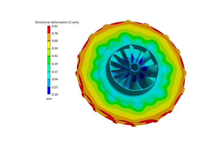
Finite Element Analysis (FEA) is a standard practice to evaluate the stress distribution and deformation of impellers under various operating conditions. This analysis helps identify potential stress concentrations and fatigue-prone areas. By optimizing the impeller’s design based on stress analysis results, we enhance its reliability and safety.
Balancing and Rotodynamic Analysis
Each impeller undergoes dynamic balancing post-fabrication and inspection to mitigate unbalanced forces and vibrations, ensuring smooth operation. Additionally, a rotating train analysis is conducted using rotodynamics to determine the critical speeds of the impeller and the entire rotating train. This analysis ensures that these critical speeds do not intersect with the normal operating speed range, guaranteeing safe and efficient operation.
Gland Seals
Gland seals feature an innovative floating seal design, incorporating precision-engineered carbon rings arranged within the seal housing. A Buffer gas connection, strategically located within the gland seal housing, positioned between the carbon rings, enables . This buffer gas connection typically utilizes low-pressure steam or treated water to further enhance the sealing performance. The buffer gas sealing ensures the pressure inside the casing as per the design and improves efficiency of the gland seals.
Bearings
The Bearings are, predominantly of the anti-friction type, with choice of pneumatic oil lubrication or pressurized oil lubrication. To ensure precise and reliable lubrication, each package is equipped with a self-contained lubrication system. The design features a configuration where two sets of bearings are positioned on one side of the rotor shaft within a sturdy pedestal and the fan impeller is expertly mounted on the opposite side of the shaft.
Vibration Monitoring
Each package comes equipped with a vibration monitoring system. This system includes a vibration sensor paired with a transmitter that seamlessly communicates with the control system. The purpose of this system is to continuously and diligently monitor the unit’s vibration levels and provide protection against any potential problems stemming from excessive vibration. Thereby it ensures smooth and reliable operation of equipment.
Electric Motor
The packages typically feature a direct-drive configuration, with the motor directly powering the fan. However, in specific project scenarios, we offer the flexibility of incorporating a speed step-up gearbox between the fan and the electric motor. This choice is made to align with the project’s unique requirements. Additionally, electric motor’s parameters, such as voltage and frequency, are selected based on the specific conditions at your site.
| Attribute | Details |
|---|---|
| Maximum Volumetric Flow | 200,000 M³/Hr @ 1 Bar, 100°C |
| Maximum Saturation Temperature Rise | 10°C |
Maxwatt also offers a range of centrifugal compressors, specially designed for applications with lower vapour flow ratings, delivering a remarkable saturation temperature rise of up to 16 Deg.C.
The impellers of these compressors are meticulously crafted using cutting-edge technology, including precision machining from solid forgings or state-of-the-art 3D metal printing processes. These impellers can be configured in both closed and open types, offering versatility to match your unique needs.
In our design, a step-up gearbox is typically incorporated, with the impellers securely mounted directly onto the gearbox’s output shaft. The input drive shaft is connected to an electric motor, ensuring efficient power transmission.
For specific cases demanding direct drive solutions, we offer the option of employing a high-speed motor, further expanding the range of possibilities to suit your requirements.
Model and Rating
| Attribute | Details |
|---|---|
| Maximum Volumetric Flow | 100,000 M³/Hr @ 1 barA, 100°C |
| Maximum Temperature Rise | 60°C |
- Maximum Volumetric Flow - 100,000 M³/Hr @ 1 barA, 100°C
- Maximum Temperature Rise - 60°C
Maxwatt Axial Steam Compressors provide high compression efficiency and are designed to handle high-volume steam compression with ease, ensuring that you get the most out of your equipment.
Our Axial Flow Steam Compressors have been expertly engineered to meet the demands of high-volume applications, delivering a remarkable saturation temperature rise between 20°C and 60°C.
Distinguished by their ingenious design, these Axial compressors incorporate multiple axial compression stages within a single casing. This innovative configuration not only provides exceptional performance but also offers a compact and efficient solution, simplifying your setup compared to the complexities associated with series-connected centrifugal compressors.
Model and Rating
| Attribute | Details |
|---|---|
| Maximum Volumetric Flow | 100,000 M³/Hr @ 1 barA, 100°C |
| Maximum Temperature Rise | 50°C |
- Maximum Volumetric Flow - 100,000 M³/Hr @ 1 barA, 100°C
- Maximum Temperature Rise - 50°C
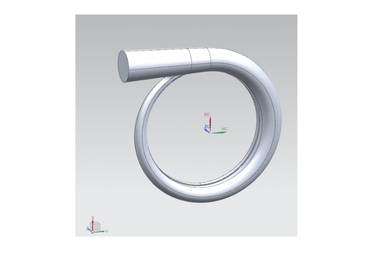
Major Components / Design & Construction Features
Volute Casing
Casing Construction
Casing Design Analysis


Material Selection
Fan Impeller
Impeller Construction


Material Selection
Material selection is driven by specific application requirements, with an emphasis on excellent mechanical properties. Commonly used materials include SS 304, SS 316L, SS 316Ti, 17-4 PH steel, Duplex, Super Duplex steel, and Titanium. Rigorous material inspections are conducted during manufacturing to ensure the absence of defects or flaws that might compromise the impeller’s integrity. Quality control measures, such as non-destructive testing (NDT) techniques like ultrasonic testing and dye penetrant inspection, are employed to verify the structural soundness of the impellers.
Stress Analysis
Finite Element Analysis (FEA) is a standard practice to evaluate the stress distribution and deformation of impellers under various operating conditions. This analysis helps identify potential stress concentrations and fatigue-prone areas. By optimizing the impeller’s design based on stress analysis results, we enhance its reliability and safety.
Balancing and Rotodynamic Analysis
Each impeller undergoes dynamic balancing post-fabrication and inspection to mitigate unbalanced forces and vibrations, ensuring smooth operation. Additionally, a rotating train analysis is conducted using roto dynamics to determine the critical speeds of the impeller and the entire rotating train. This analysis ensures that these critical speeds do not intersect with the normal operating speed range, guaranteeing safe and efficient operation.
Gland Seals
Gland seals feature an innovative floating seal design, incorporating precision-engineered carbon rings arranged within the seal housing. A Buffer gas connection, strategically located within the gland seal housing, positioned between the carbon rings, enables . This buffer gas connection typically utilizes low-pressure steam or treated water to further enhance the sealing performance. The buffer gas sealing ensures the pressure inside the casing as per the design and improves efficiency of the gland seals.
Bearings
The Bearings are, predominantly of the anti-friction type, with choice of pneumatic oil lubrication or pressurized oil lubrication. To ensure precise and reliable lubrication, each package is equipped with a self-contained lubrication system. The design features a configuration where one / two sets of bearings are positioned on one side of the rotor shaft within a sturdy pedestal and the fan impeller is expertly mounted on the opposite side of the shaft.
Vibration Monitoring
Each package comes equipped with a vibration monitoring system. This system includes a vibration sensor paired with a transmitter that seamlessly communicates with the control system. The purpose of this system is to continuously and diligently monitor the unit’s vibration levels and provide protection against any potential problems stemming from excessive vibration. Thereby it ensures smooth and reliable operation of equipment.
Electric Motor
The packages typically feature a direct-drive configuration, with the motor directly powering the fan. However, in specific project scenarios, we offer the flexibility of incorporating a speed step-up gearbox between the fan and the electric motor. This choice is made to align with the project’s unique requirements. Additionally, electric motor’s parameters, such as voltage and frequency, are selected based on the specific conditions at customer site.

